NANOPATCH M is unique among DF Audio patch bays in that it does not require insert cables for connecting to external gear (although this is also an option).
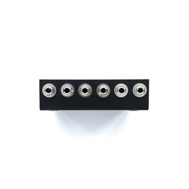
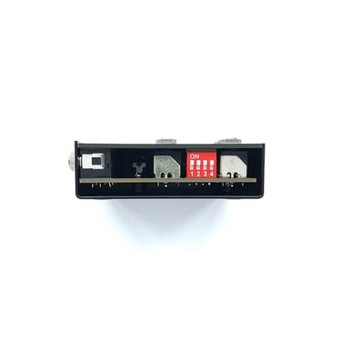
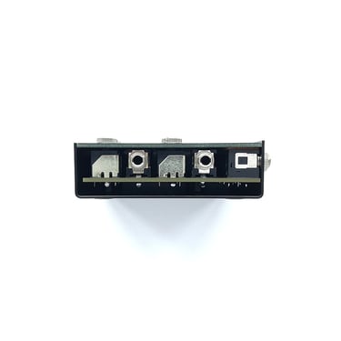
It has eight 3.5 mm jacks on the back/side (four TRS and four TS) which correspond to eight 3.5 mm TS sockets on the top panel, and normalling switches.
NANOPATCH M is ideal for connecting to instruments and a mixer when used together with NANOPATCH X, and is a great companion to MINIBAY V2 (to connect to small instruments with minijack audio outputs).
It also works with CV, so it can be a useful tool for instruments with patch points in hard-to-reach places (e.g. Moog Grandmother).
DESCRIPTION: 8-point patch bay
BACK PANEL: 4 x 3.5 mm TRS sockets; 4 x 3.5 TS sockets
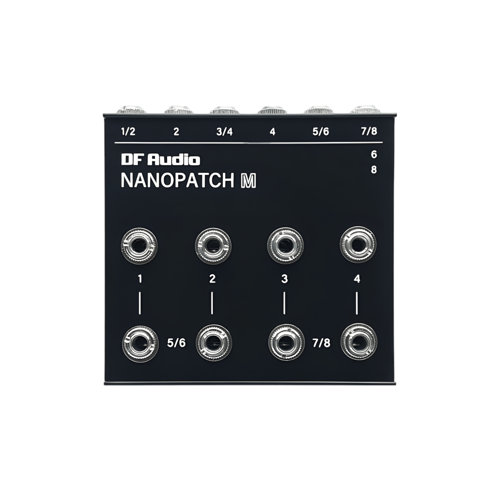
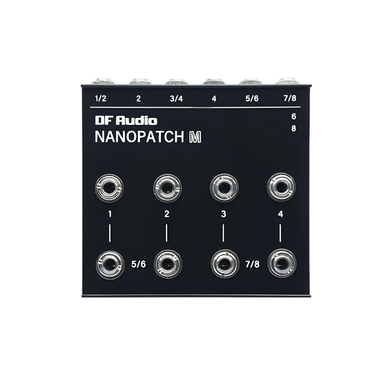
TOP PANEL: 8 x 3.5 mm TS sockets
NORMALLING: Yes
COMPATIBLE SIGNALS: Audio, CV, MIDI
DIMENSIONS: 76 mm x 70 mm x 22mm
WEIGHT: 150 g
NANOPATCH M
NANOPATCH M


Dud Faz' NANOPATCH X & M tutorial
Quick NANOPATCH demo
Robin Vincent on NANOPATCH X & M
Sockets on the back labelled with two numbers (e.g. "1/2") are TRS. When a TRS cable is plugged into one of these, the signal breaks out to the two corresponding sockets on the top panel (e.g. "1" and "2").
When a second cable is plugged into the next socket on the back (e.g. "2"), this overrides the signal with the same number on the first socket. Thus, socket "1/2" on the back will go to "1" on the top panel, and socket "2" on the back will go to "2" on the top panel.
This means that NANOPATCH M can operate like a traditional patch bay, with one-to-one correspondence between both panels.
Normalling switches are located on the side. When engaged, signals can flow between connected devices without needing to be patched. These connections are marked with lines on the top panel (1-5, 2-6, etc.). When a patch cable is plugged into a socket on the top panel, the respective normalled connection is broken.
How IT WORKS
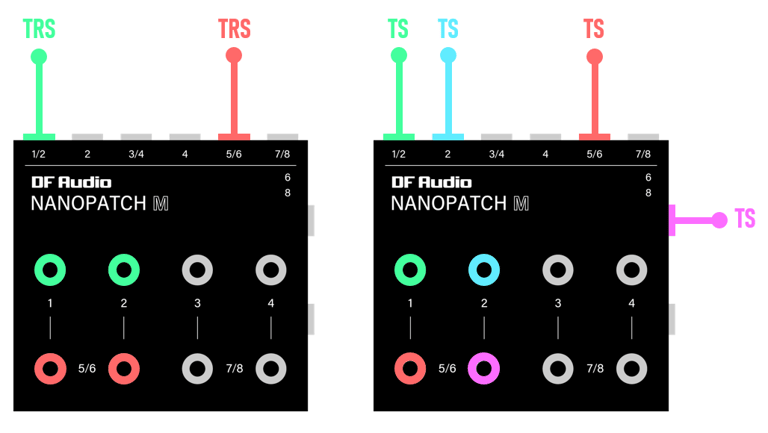
Correspondence between back/side and top sockets on NANOPATCH M
NOTE: TRS cables can be safely used with TS configuration (right)
Here's how the TRS sockets on the back of NANOPATCH M are connected to the corresponding patch points on the top panel: TIP - left socket; RING - right socket
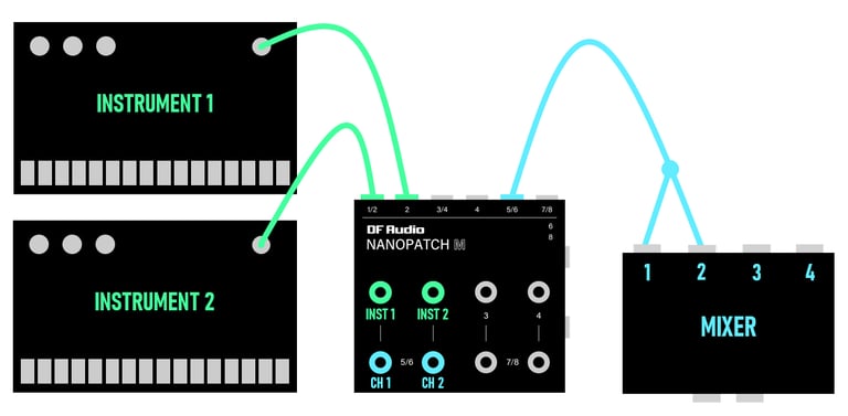
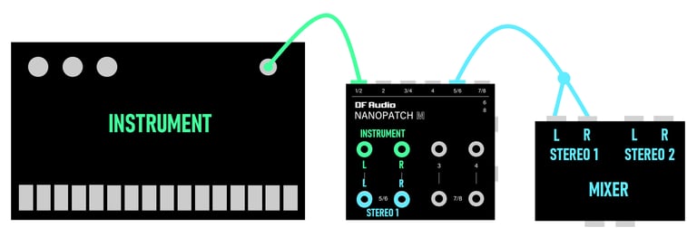
Instruments and mixer connected in mono
Instrument and mixer connected in stereo
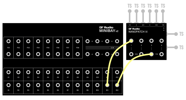
NANOPATCH M with MINIBAY V2
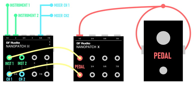
NANOPATCH M with NANOPATCH X
How IT WORKS
Instruments and mixer connected in mono
Instrument and mixer connected in stereo
NANOPATCH M with MINIBAY V2
NANOPATCH M with NANOPATCH X