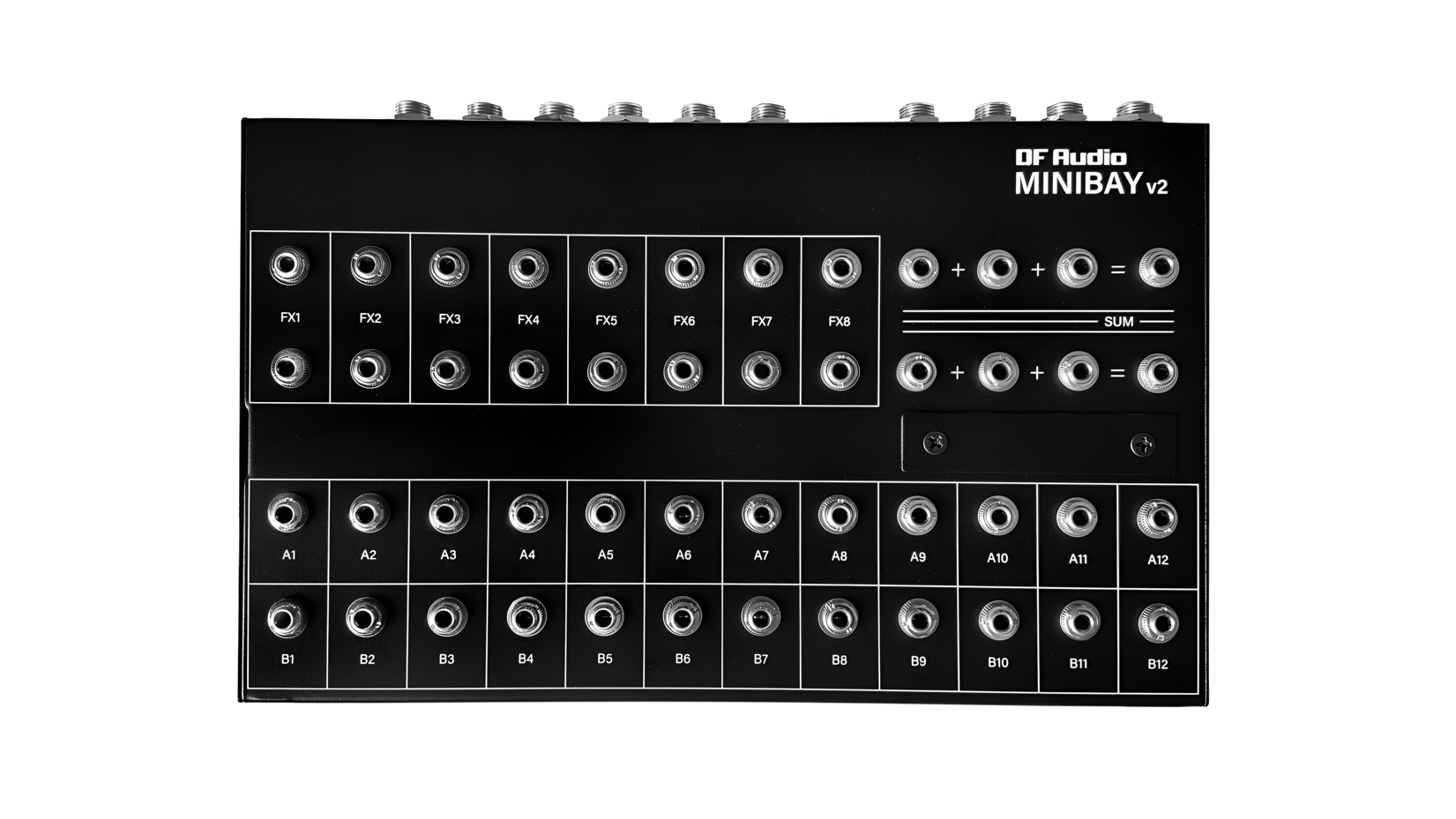
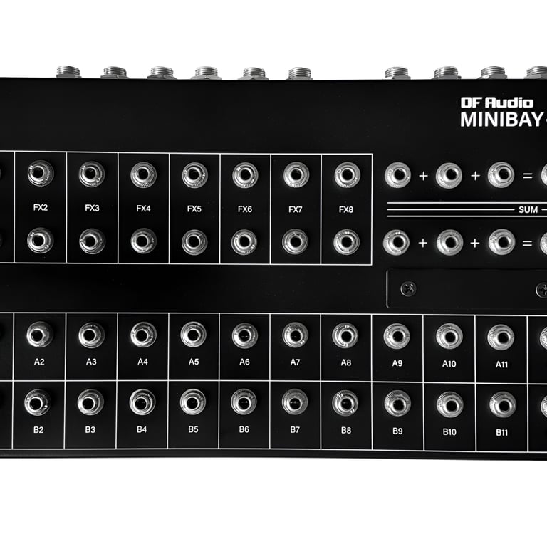
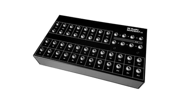
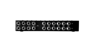
MINIBAY V2 is a compact 40-point patch bay designed to integrate neatly into a studio desktop space.
It has twenty 6.35 mm TRS sockets on the back, each of which break out into two 3.5 mm TS sockets (eurorack style) on the top panel.
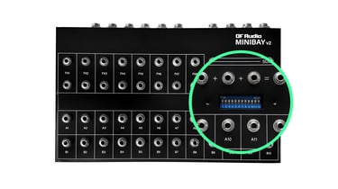
Twelve normalling switches for A/B rows can be easily accessed via the top panel.
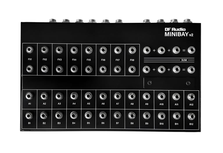
It also features two 3-channel passive mixers, each with four dedicated I/O patch-points.
DESCRIPTION: 40-point patch bay
BACK PANEL: 20 x 6.35 mm TRS sockets
TOP PANEL: 48 x 3.5 mm TS sockets
NORMALLING: 12 x A/B pairs (optional)
MIXERS: 2 x 3-channel, passive
COMPATIBLE SIGNALS: Audio, CV, MIDI
DIMENSIONS: 234 mm x 140 mm x 40 mm
WEIGHT: 1.3 kg
minibay v2
minibay v2


MINIBAY OG tutorial
MINIBAY V2 demo by Your City Sleeps
Bo Beats explains patch bays (feat. MINIBAY OG)
With the rise of desktop synths and compact (or not-so-compact) dawless setups, many find the need for a patch bay, but are put off by the idea of bringing an unwieldy rack-mount unit into their rig.
MINIBAY V2 takes the power of a traditional patch bay and puts it into an elegant and intuitive design that invites exploration using easy-to-manage 3.5 mm patch cables.
The small footprint means that it can be positioned just next to a mixer for easy use and quick reference to where signals are routed.
PATCH BAYS IN A NUTSHELL
A patch bay is essentially a hub in your setup, to which various pieces of gear (instruments, effects, mixer, etc.) are connected. From here, it is easy to direct where signals go, by making connections with patch cables.
Generally, there are two main reasons for wanting to do this:
> You have more instruments than channels available on your mixer
> You like to change which effects are used on various instruments and/or experiment with different effect chains.
There are also many other uses. For more about the concept of patch bays, how they work, and the advantages they offer, check out Bo's video (above).
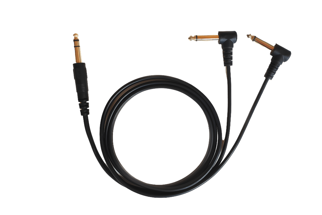
In most cases, connections to instruments, effects and a mixer are made with TRS to dual TS cables, AKA insert cables.
This system allows two TS (mono) connections for each TRS socket on the back panel, and is how MINIBAY V2 is able to pack so much punch for its size.
TRS-TRS cables can be used to make stereo or balanced connections. When this is done, each L/R channel or polarity must be patched separately on the top panel.
The diagram below lays out the beginnings of a typical MINIBAY V2 setup. Let's walk through it...
why mini?
HOW IT WORKS
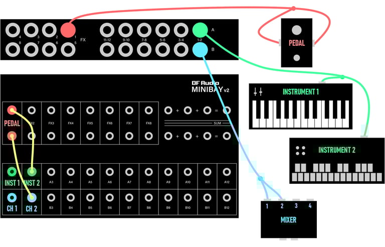
Typical MINIBAY V2 setup
Starting at the top in RED, the TRS end of an insert cable is plugged into the FX1 socket on the back panel. One of the TS ends is plugged into the input of the pedal and the other into its output.
The two patch points in the FX1 slot on the top panel represent the input and output of the pedal (notice the vertical arrangement).
Next, we have a GREEN insert cable going from A1-2 on the back panel to the outputs of two separate instruments. Patch points A1 and A2 on the top panel represent the outputs of each instrument.
In BLUE, socket B1-2 on the back panel is connected to the inputs of channels 1 and 2 on the mixer. Those inputs are represented by patch points B1 and B2 on the top panel. (Notice the horizontal arrangement for the A/B patch point pairs).
We have two instruments on row A and two mixer channels directly below them on row B. Using patch cables, we can take the output of INSTRUMENT 2 up to the input of the PEDAL, then from the output of the PEDAL down to the MIXER CH 2 input.
If normalling is enabled for A/B-1, then INSTRUMENT 1 will go straight through to MIXER CH 1. This normalled connection will be broken if a patch cable is plugged into either A1 or B1 on the top panel.
Remove the two screws on the top panel to access the normalling switches.
Some insert cables have the TS ends labelled TIP and RING to indicate which part of the TRS end they correspond to. On others, you need to figure it out yourself (and it's a good idea to mark them once you have).
Here's how the TRS sockets on the back of MINIBAY V2 correspond to the patch points on the top panel:
FX: TIP - upper socket; RING - lower socket
A/B: TIP - left socket; RING - right socket
patching
FX ROWS
a/b ROWS
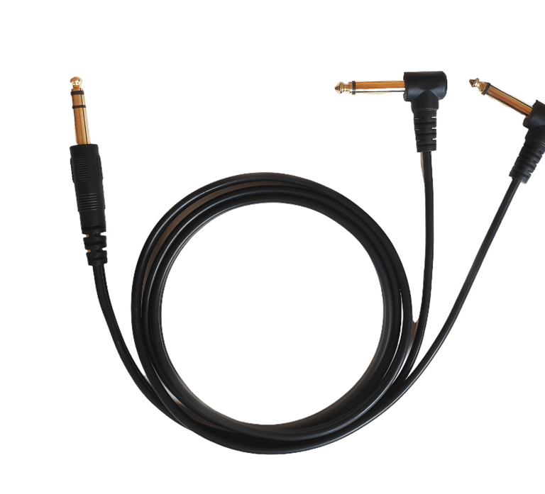
TRS to dual TS (insert) Cable
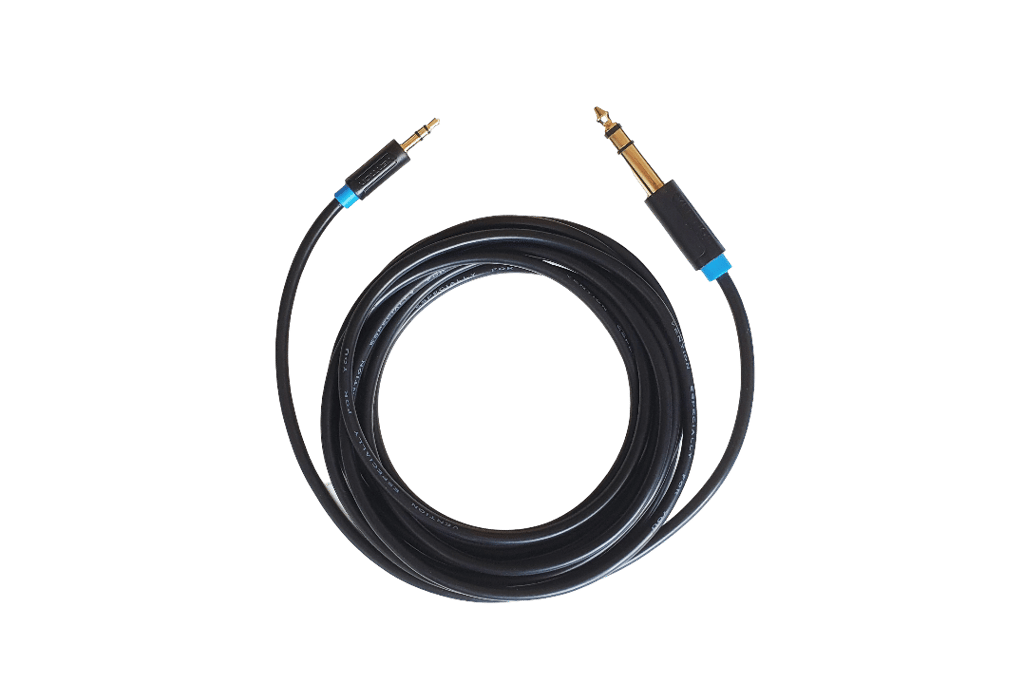
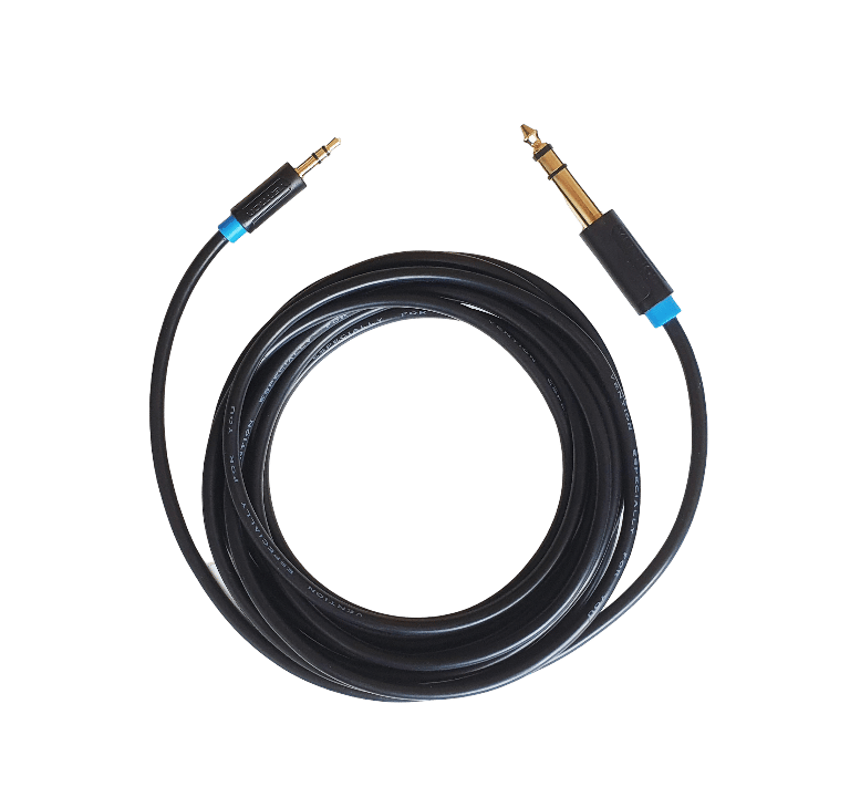
TRS to TRS Cable
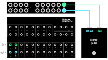
Regular stereo pedal on FX rows
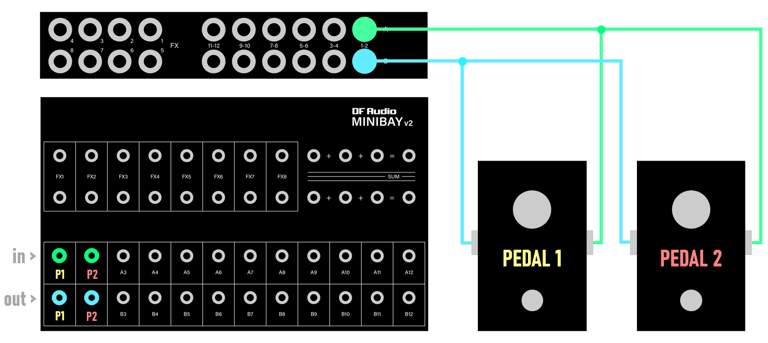
TRS stereo pedal on A/B rows
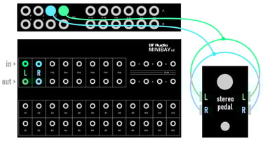
Mono pedals on A/B rows